PIC Beginnings
May 12, 2019 electronics pic
It's been far longer than I intended to post this follow up. I received my order of PICs and the PICkit 4 some time ago, and set to playing.
First up, downloading the software. Microchip provide MPLAB X for free to work with their chips, and I saw no reason not to use it. When you start it up and create a new project, you can choose exactly which chip you're targetting. In my case this is the PIC18F27K42, which seemed to be a good balance of not too many pins plus had more than one UART, so I can potentially practice chaining them together in a communication array (remember, at some point I'm supposed to be working towards having 4 neighbours on each block, but I'm still learning to walk here, so 2 is plenty).
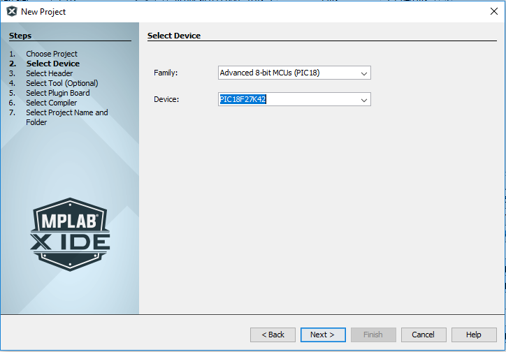
After choosing the chip type, you can then select the programmer you're intending to use - in my case the PICkit 4 - followed by the compiler you wish to use. There seems to be a choice of 2, those being C18 and XC8. A bit of googling led me to use XC8, simply because it's the newer one and appears to be the way things are heading. I'm sure there are reasons to pick the old one if you need it, but I'm unaware of what those reasons might be so stuck with "newer is better"!
Finally you choose your project name and where you want it to live on disk. That gives you a nice empty project to start with.
At this point, I was vaguely aware that I need to set various configuration bits to get the chip to even function, and it was part of the process I wasn't looking forward to. Luckily, it wasn't long before I found out about the "MPLAB® Code Configurator". You can choose it as a plugin in the X IDE, installed earlier. Once invoked, it displays various config screens for the chip you selected for your project.
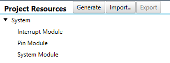
For my chip, there were 3 core system modules available by default - the Interrupt Module, the Pin Module, and the System Module.
Starting off in the System Module, you can set the basics such as the oscillator to use. Another thing about the chips I selected, and may be the case for many/most/all PICs (I have no idea), is that they have a high frequency internal oscillator - no need for a highly accurate external resonator or crystal, at least not for the type of work I'm doing to begin with. I set it to 64MHz, the highest available for this chip (because why not? I'm not running off batteries at this stage - may as well run it full tilt!)
Next up was the Pin Module - I knew the first thing I wanted to do was to get an LED blinking - the Pin Module lets you define which pins are inputs and outputs (amongst other things). I picked Port A bit 0 and set it as an output. Once you're happy with the config, you hit the generate button and it goes off to create various header and source files that get included in the project to set all the configuration bits properly. Some other things, such as the timers (which I'll get on to below), also create boiler plate code for you.
It was around here that I noticed the handy "map" it gives you of the pins of your device:

Handy when it comes to layout things out on the breadboard! Speaking of which, it was time to wire it up. First off I tied all the power pins to the +5V and ground rails, as needed. I added a 100nF capacitor as close to the chip as I could between the +5V and ground pins 20 & 19. MCLR got tied to ground via a small resistor and capacitor, and to +5V via a larger resistor, as described in the recommended minimum connections in the datasheet. I added a further resistor and LED to pin 2, that of Port A bit 0. Finally I brought all 5 pins needed for programming to 5 adjacent columns on the breadboard, and added a header so that the PICkit was easy to connect.
I first wanted to get the LED flashing - to achieve this there were a couple of routes I could take. The first route was to write a simple program that counts to a high number, then turns the pin on, then counts again before turning it off:
while (1)
{
    for (long x = 0; x < 500000; x++);
    LATAbits.LA0 = 1;

    for (long x = 0; x < 500000; x++);
    LATAbits.LA0 = 0;
}
While this works, it's not exactly great - the CPU is busy counting with no time to do anything else. Time to start using a timer - back to the Code Configurator. As well as listing the features already being used, below it also lists all available resources (features/peripherals etc). Double clicking on TMR0 (the first timer), adds it to the list of the ones in use, and allows configuration of it:
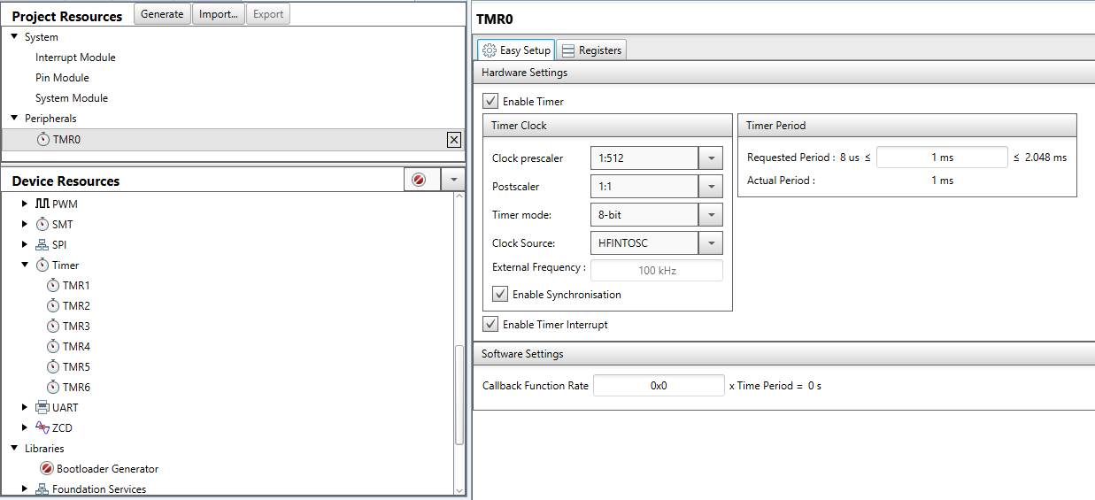
It took a little bit of poking, but I soon realised that by changing the settings on the left, it gave me a range in which I could then choose an exact time from on the right. The range available to me with the settings I chose was 8 microseconds to 2.048 milliseconds - great, I wanted to fire every millisecond. Having set this up, I hit generate again, and went off to look at the files it had created for me. Reading through those files, I found I could get it to call back my own defined function quite simply:
TMR0_SetInterruptHandler(MillisecondTimer);
And with that, a simple function to blink the LED on and off exactly every half-second:
int count = 0;
void MillisecondTimer(void){
    count++;
    if (count == 500) {
        LATAbits.LA0 = 1;
    } else if (count == 1000) {
        LATAbits.LA0 = 0;
        count = 0;
    }
}
I could of course for this have changed the timer settings to just fire every half second in the first place - no need for the counter, but I can foresee the need for a millisecond timer at some point so wanted to try this route out.
The final piece of the basic jigsaw is reading inputs. Back to the pin module, and I set Port B bit 0 as an input, along with ticking the WPU box - this tells it to use a pull-up resistor internally. I added a momentary push button between it (pin 21, my handy map tells me) and ground. All this means that the pin will read high when the button is not pressed, and low when it is. The updated code:
int count = 0;
void MillisecondTimer(void){
    count++;
    if (count == 500) {
        LATAbits.LA0 = 1;
    } else if (count == 1000) {
        if (PORTBbits.RB0) {
            LATAbits.LA0 = 0;
        }
        count = 0;
    }
}
The LED still blinks every second, but if you hold the button down, it will not switch off.
Here's the circuit in all it's glory:
Note the extra power supply on the left - right now the circuit is being powered by the PICkit (there's an option of whether to power the circuit from the PICkit or not), but the breadboard can also be powered via a plug-in adapter via the supply on the left.
Next up I'd like to test a couple of things. Firstly, getting the button press itself to trigger an interrupt. Then duplicating the entire circuit further along the breadboard, and adding links coupling the UART serial links together. The goal at that stage will be to have the button on one chip cause the flashing to pause on the other chip.
Nice small steps!
Back to posts